
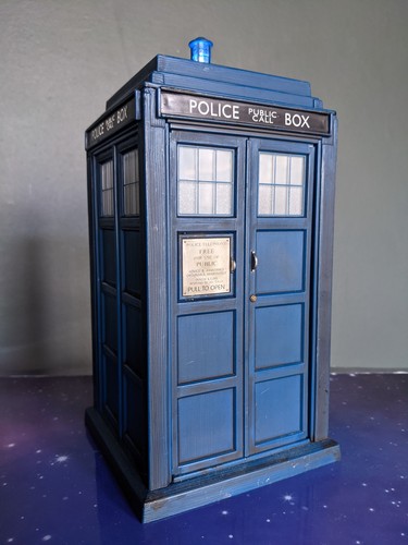
The whole project actually started with a TARDIS. The first version was very simple: the Raspberry Pi 4 only had to drive the small lamp on the roof. Later I swapped to a better model with illuminated windows and the Police Public Call Box sign, and that small upgrade was what really started the chain reaction. Once I had spare Raspberry Pi GPIO, a tidy ribbon cable already running up the shelves and a few lighting ideas in mind, it became hard not to keep adding more.
The shelves gradually turned into a small automation project of their own. The TARDIS was followed by the LEGO Star Wars Executor Super Star Destroyer (75356), the LEGO Icons McLaren MP4/4 & Ayrton Senna (10330), the LEGO Speed Champions Time Machine from Back to the Future (77256), and now plans for a much larger DeLorean build. Each model added a slightly different requirement: direct LED control, 5 V switching, dim evening modes, breathing effects, schedules and eventually the need for more outputs than the Pi wiring could comfortably provide.
This post documents the current logic, the ideas I considered, the compromises, and the end point I am working towards: a compact ESP32 model lighting controller that keeps the Raspberry Pi as the master while giving the shelves more local outputs and far more flexible lighting control. The finished six-channel build is now documented in From Raspberry Pi Relays to an ESP32 MOSFET Model Lighting Controller.
Where the project started
The current shelf arrangement already works well, so the aim is not to rip everything out for the sake of it. The Raspberry Pi 4 remains the central controller, with the existing 10-way ribbon cable neatly routed up the wall and broken out at different shelves.
- Bottom shelf: McLaren model lighting.
- Middle shelf: Vader / Executor ship lighting, which is simple enough to remain directly controlled from the Pi.
- Top shelf: the current relay board, spare breakout wiring, the mini DeLorean controller and eventually the larger DeLorean.
The McLaren is the interesting one. Its lighting kit is happiest at 5 V and is very bright at full power. During the evening I prefer a softer effect, and the existing setup achieves that by switching between full 5 V operation and a lower-voltage mode. I also occasionally run breathing effects just because it looks good.
The problem with simply adding more relays
A larger relay board would certainly work. It would also be familiar and very forgiving: an ESP32 or Pi GPIO energises a relay and the relay bridges the 5 V supply to the model. For simple on/off lighting, there is nothing inherently wrong with that.
The limitation is that a relay is fundamentally an on/off device. It cannot smoothly dim a model, breathe the lights, fade them up at sunset or create fast lighting sequences without becoming noisy and mechanically busy. Adding more relay channels also means more board space and more current just to energise the relay coils.
The alternative: keep 5 V on the models and switch with MOSFETs
The cleaner approach is to leave each lighting kit connected to the 5 V supply it was designed for and place an N-channel MOSFET in the return path. The ESP32 only supplies a 3.3 V control signal to the MOSFET gate. The ESP32 is not powering the model directly.
That distinction is important: 5 V powers the lights; 3.3 V controls the switch.
Why bring an ESP32 into the middle?
The Pi has already used most of the practical GPIO paths available through the existing ribbon arrangement. Running more individual wires would defeat the point of the tidy installation. This is also a natural progression from my earlier ESP32-C3 wireless light-control project, where moving local lighting functions away from the Pi proved how useful a small ESP controller can be.
An ESP32 solves that problem by acting as a local I/O multiplier. The Pi only needs one command path to the ESP32 — MQTT over Wi-Fi, or a hardwired GPIO/UART link if I decide I want a fallback — and the ESP32 can then fan that command out to several local lighting channels.
Brainstorming the options
I considered several routes before settling on the current direction:
- Keep adding relays: reliable and simple, but on/off only and physically bulky.
- Drive each LED directly from GPIO: possible for carefully current-limited individual LEDs, but not ideal when the lighting kits are already designed around 5 V.
- Use a GPIO expander on the Pi: attractive for extra digital outputs, but it does not solve the local PWM/effects requirement as cleanly as an ESP32.
- Use an ESP32 plus MOSFETs: keeps the 5 V model supplies intact, gives local PWM, and creates room for more models without more long cable runs.
The first three channels
The first stripboard will be deliberately simple: three MOSFET channels, one each for the McLaren, mini DeLorean and future larger DeLorean.
| Channel | Load | Planned functions |
|---|---|---|
| 1 | McLaren | Off, full brightness, evening dim, breathing |
| 2 | Mini DeLorean | Existing modes, breathing, coordinated effects |
| 3 | Big DeLorean | Reserved until the new light kit is known |
The current component choice for the low-side switches is the IRLZ44N. It is a large TO-220 device and wildly over-specced for a few model LEDs, but it is cheap, easy to solder on stripboard and forgiving for a first version. Each channel gets a 220 Ω gate resistor and a 10 kΩ pull-down.
Minimal prototype BOM
| Part | Qty used | Notes |
|---|---|---|
| Existing ESP32 | 1 | Reuse the mini DeLorean controller |
| 64 × 95 mm stripboard | 1 | Main controller card |
| 2.54 mm female headers | 2 rows | Keeps ESP32 removable |
| IRLZ44N MOSFET | 3 | One per lighting channel |
| 220 Ω resistor | 3 | ESP32 GPIO to MOSFET gate |
| 10 kΩ resistor | 3 | Gate pull-downs |
| 470 µF electrolytic | 1 | Across 5 V/GND near ESP32 |
| 100 nF ceramic | 2–3 | Local decoupling |
| Screw terminals / JST | As required | Power and removable model connections |
Hardware used
The first version is intentionally simple and uses parts that are easy to source and easy to replace. I keep a broader list of the kit used around the lab on the Realm Labs hardware page, but the parts for this controller are:
- Raspberry Pi 4 as the master controller
- Existing ESP32 as the local lighting controller
- 64 × 95 mm stripboard
- 2.54 mm female headers so the ESP32 remains removable
- 3 × IRLZ44N N-channel MOSFETs
- 3 × 220 Ω gate resistors
- 3 × 10 kΩ gate pull-down resistors
- 1 × 470 µF electrolytic capacitor across the 5 V rail
- 2–3 × 100 nF ceramic capacitors for local decoupling
- Screw terminals or JST-style connectors for 5 V, GND and model outputs
- Existing 5 V supply and shared ground
- Optional future MAX98357A I²S DAC/amplifier and small speaker
The physical models currently tied into the wider setup are the LEGO Icons McLaren MP4/4 & Ayrton Senna 10330, the LEGO Star Wars Executor Super Star Destroyer, the LEGO Speed Champions Back to the Future Time Machine, plus the TARDIS that started the whole chain of experiments.
How control will work
The Raspberry Pi stays in charge of the automation logic. Node-RED can continue to decide what happens at sunrise, sunset, late evening or on demand. Instead of each action consuming another physical Pi GPIO line, the Pi sends a command to the ESP32. That keeps the same orchestration approach I already use elsewhere in the lab while moving the time-sensitive lighting work closer to the models.
Example logical commands might look like:
mclaren/full
mclaren/evening
mclaren/breathe
mclaren/off

mini/on
mini/breathe
mini/time_travel

big/on
big/time_travel

models/all/off
MQTT is the obvious transport because it already fits the rest of the lab and ties directly into my existing MQTT model control panel. The broker itself is already part of the wider Synology MQTT setup, but I am also leaving the possibility of a direct hardwired Pi-to-ESP control line if I decide I want the lighting to remain independent of Wi-Fi.
Future audio
The ESP32 also gives the project somewhere sensible to grow. If the larger DeLorean deserves sound later, I can reserve a small five-pin header for an MAX98357A I²S DAC/amplifier.
Final schematic
The end-state wiring is deliberately straightforward: the Raspberry Pi remains the master, the ESP32 provides the local GPIO, and each model keeps its proper 5 V supply while an individual MOSFET switches the return path. That gives independent on/off control plus PWM dimming and breathing without adding more relay boards.
The eventual end point
The finished system should be simpler than the collection of individual hacks that led to it, while retaining everything that made those hacks useful.
- The Raspberry Pi 4 remains the master for schedules, Node-RED and wider automation.
- The ESP32 becomes the local lighting controller for the top-shelf group.
- Each model keeps its intended 5 V lighting supply.
- MOSFET channels provide on/off, PWM dimming, breathing and custom effects.
- The existing Executor lighting remains untouched because it already works perfectly well directly from the Pi.
- More channels can be added later without pulling another large bundle of cable through the shelving.
- I²S audio can be added when there is a model worth giving a voice.
The main lesson from the brainstorming has been that I do not need a more complicated controller — I need a cleaner separation between logic and power. The Pi decides what should happen, the ESP32 provides the local intelligence, the MOSFETs switch the 5 V loads, and the models simply do what they are told.
That gives me a small, cheap controller today and a much easier route to adding the next DeLorean tomorrow.
Featured photo by Vishnu Mohanan on Unsplash.