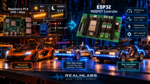

My model lighting setup didn’t start with an ESP32, MQTT effects or PWM control. It started with a Raspberry Pi 4, a GPIO output and a relay.
The original arrangement controlled the lighting kit fitted to my McLaren model. A GPIO from the Pi energised a relay, which in turn connected the light set to its 5 V supply. It worked, but at 5 V the lighting was much brighter than I wanted in the evening.
Rather than rebuild the controller immediately, I used the relay contacts to give me a crude second brightness level. During the day the relay supplied 5 V. At sunset, Node-RED deactivated the GPIO and the relay fell back to a 3.3 V feed instead. Simple, slightly crude, but effective.
The first version: Pi GPIO and relay
DAY
Pi GPIO ON
   ↓
Relay energised
   ↓
5 V to McLaren lights
   ↓
Full brightness

EVENING
Pi GPIO OFF
   ↓
Relay released
   ↓
3.3 V to McLaren lights
   ↓
Reduced brightness
For one model and two brightness levels, this was enough. The Raspberry Pi already handled the automation and Node-RED already knew when sunset occurred, so the relay solved the original problem with very little extra hardware.
Then I added the Mini DeLorean
The limitations became obvious when I added the Mini DeLorean. I didn’t just want one light circuit with a bright and dim state. I wanted separate control of the front and rear illuminated rails, independent brightness, smooth fades, a front-to-back breathing effect and a faster alternating lighting mode.
At that point, adding more relays stopped making sense. I wanted proper electronic lighting control while keeping the Raspberry Pi and Node-RED as the higher-level automation layer.
Why move the lighting outputs to an ESP32?
The Raspberry Pi still has a useful role. Node-RED handles sunrise, sunset, schedules, manual controls and effect selection. MQTT then carries those commands to the ESP32, which handles the real-time lighting outputs locally.
Raspberry Pi / Node-RED
        │
        │ MQTT
        ▼
      ESP32
        │
        ├── PWM channel
        ├── PWM channel
        ├── PWM channel
        └── more channels
This split also means an effect can continue running on the ESP32 even if Node-RED or MQTT briefly disappears.
Why MOSFETs instead of relays?
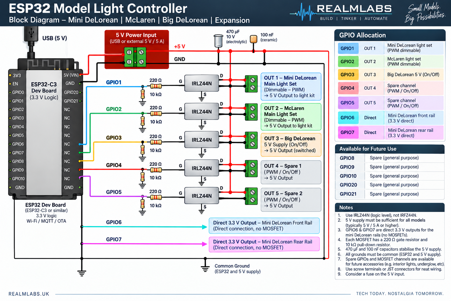
A relay is ideal for simple on/off switching. It is less useful when I want smooth brightness control. Moving to MOSFETs means the ESP32 can use PWM to control each lighting channel electronically.
Instead of choosing between 5 V and 3.3 V, I can now request anything from off to full brightness while keeping the lighting supply itself at 5 V.
0%
20%
40%
60%
80%
100%
The basic MOSFET channel
                     +5 V
                       │
                 Model lights
                       │
                     Drain
                       │
                   IRLZ44N
                       │
                    Source
                       │
                      GND

ESP32 GPIO
     │
    220Ω
     │
    Gate
     │
    10kΩ
     │
    GND
Each GPIO drives the MOSFET Gate through a 220 Ω resistor, while a 10 kΩ resistor pulls the Gate to ground so the channel remains off while the ESP32 is starting or whenever the pin is not actively driven.
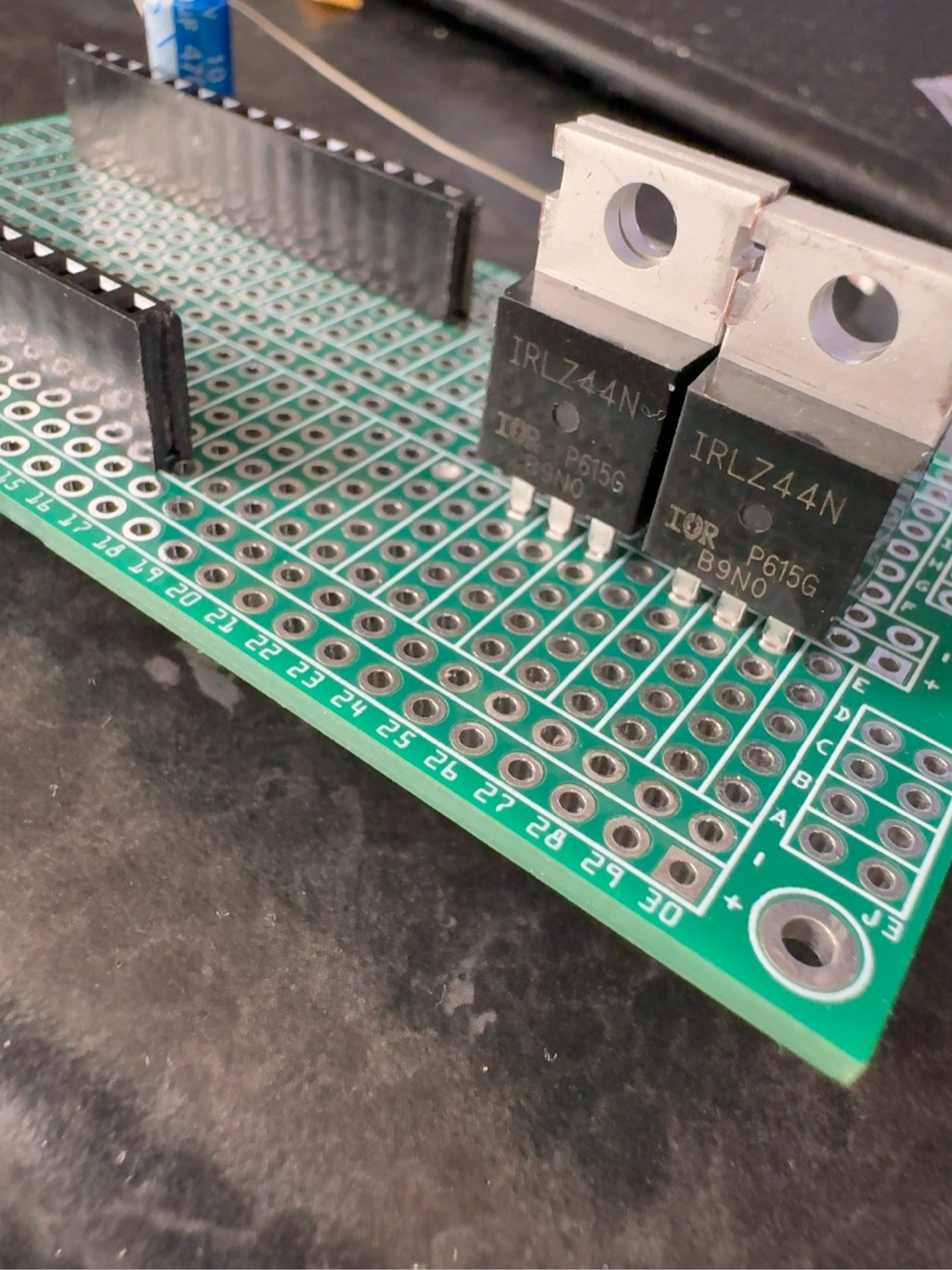
For the IRLZ44N devices I used, viewed from the front with the writing facing me, the pins are Gate, Drain, Source from left to right. The metal tab is also electrically connected to the Drain.
Building the controller on prototype board
I used a small FR4 prototype board and female headers so the ESP32 can be removed rather than permanently soldered in place. That makes changes and replacement much easier while the design is still evolving.
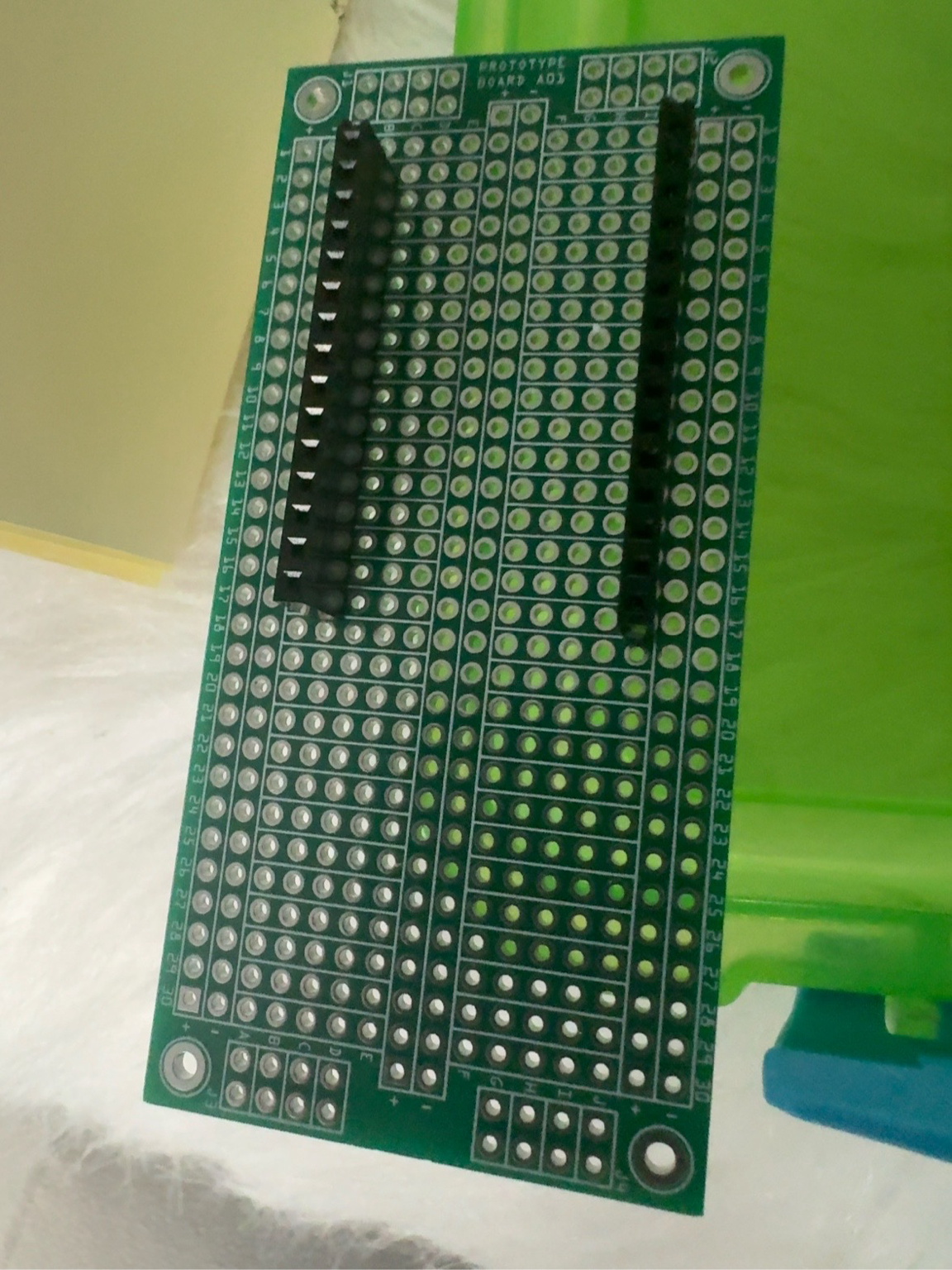
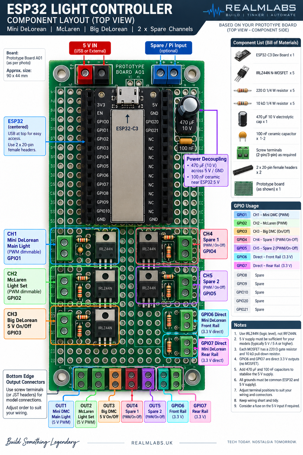
The final six-channel wiring
The finished controller uses six MOSFET channels. I ran the model connections over an eight-core Ethernet cable, using six cores as switched negative returns and the remaining two as a shared 5 V feed.
| Ethernet core | ESP32 GPIO | Use |
|---|---|---|
| Orange | GPIO10 | Mini DeLorean main |
| Green | GPIO3 | Mini DeLorean front rail |
| Green/White | GPIO2 | Mini DeLorean rear rail |
| Blue/White | GPIO4 | McLaren |
| Blue | GPIO6 | Main / large DeLorean |
| Brown/White | GPIO7 | Spare |
| Orange/White | — | +5 V |
| Brown | — | +5 V |
Using two conductors for the common positive feed gives the shared 5 V supply more copper because it carries the combined current of the active lighting channels. Each model then returns through its own MOSFET-switched negative conductor.
Mini DeLorean lighting modes
The Mini DeLorean now has three useful styles of operation.
Independent front and rear control
The front and rear rails can each be switched on, off or assigned their own brightness percentage.
Front = 30%
Rear  = 70%
Breathing mode
The original effect fades smoothly from front to rear and then back again, with one rail rising as the other falls.
Fast alternating mode
A second effect rapidly alternates the front and rear rails rather than flashing them together, creating a much more animated look.
Front ON / Rear OFF
        ↓
Front OFF / Rear ON
        ↓
      repeat
The McLaren gets proper dimming too
The McLaren no longer needs a relay to swap between 5 V and 3.3 V. Its ESP32 channel can simply be told what brightness to use over MQTT.
mclaren/light/set = 100
mclaren/light/set = 40
mclaren/light/set = OFF
MQTT and Node-RED
The Mini DeLorean mode topic is:
minidelorean/set
with commands including:
ON
OFF
BREATHING
FLASHING
The front and rear rails can also be addressed individually through minidelorean/front/set and minidelorean/rear/set.
The McLaren uses mclaren/light/set, while a separate channel is already provisioned for the larger DeLorean. Its final implementation will depend on how I integrate the existing remote-control electronics.
Sunrise, sunset and automatic effects
Node-RED still handles the schedule that started this whole project. At sunrise the lights can come on and settle into their normal breathing mode. During the day, random effects can be introduced. At sunset a different effect can run, and at 23:00 the display shuts down.
SUNRISE
   ↓
ON
   ↓
BREATHING
   ↓
DAYTIME EFFECTS
   ↓
SUNSET
   ↓
EVENING EFFECT
   ↓
23:00
   ↓
OFF
What stayed on the Raspberry Pi?
Not everything needed to move. The existing Executor lighting remains directly controlled by the Raspberry Pi because it already works perfectly well. The ESP32 is an expansion of the Pi setup, not a replacement for it.
Hardware used
- Raspberry Pi 4 — see my Hardware page
- ESP32-C3 — also listed on the Hardware page
- IRLZ44N MOSFETs
- 220 Ω ¼ W resistors
- 10 kΩ ¼ W resistors
- 100 nF ceramic capacitors
- 470 µF 10 V electrolytic capacitor
- FR4 prototype board
- 2.54 mm female header strip
- Eight-core Ethernet cable
- Connectors and terminals
I’ll add the individual component links once the finished controller has had some time in service and I’m happy with the parts I used.
A useful evolution rather than a complete redesign
I don’t consider the original relay solution a mistake. For one model and two brightness levels it was quick, inexpensive and reliable. The problem simply changed as the display grew.
Moving the new lighting outputs onto an ESP32 and MOSFETs gives me six independently controlled channels, proper PWM brightness control and much more scope for effects, while the Raspberry Pi, Node-RED and MQTT all remain in service.
Related Realm Labs projects
This controller builds on several earlier Realm Labs projects. The original thinking is documented in Building a Smarter Model Lighting Controller with ESP32 and MOSFETs. For the wider control stack, see Taking Light Control Wireless with the ESP32-C3, Physical Home Automation with Node-RED, Raspberry Pi 4 and Synology, Building a Mobile MQTT Control Panel for My Home Lab Models, and Mosquitto MQTT on Synology. The wider model-lighting idea also grew out of the Smart TARDIS project.
That is probably a fair description of most of my homelab projects: start with the simplest thing that works, discover why it is no longer enough, and then build the next version.