
If you’ve spent any time tinkering with home automation or DIY electronics, you know how easy it is to fall down the rabbit hole. What starts as a simple single-board setup—like running Home Assistant or Node-RED routines off a Raspberry Pi 4—quickly turns into wanting to control every light, switch, and sensor in the house.
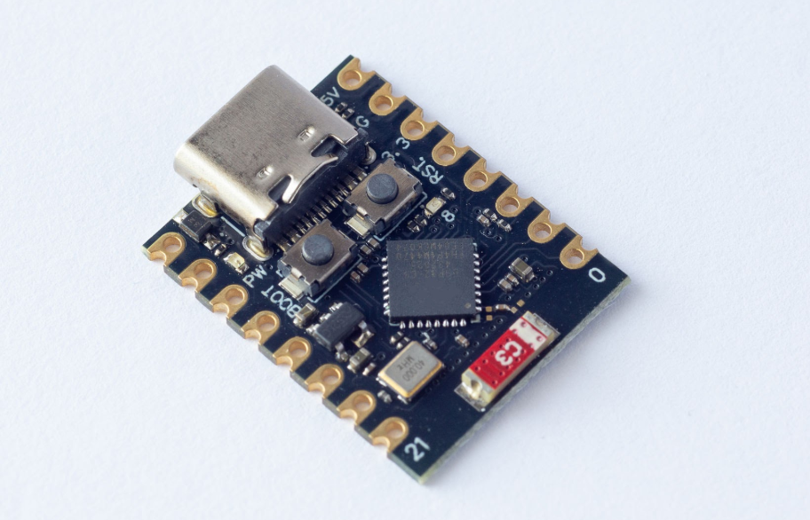
While the Pi 4 is an absolute workhorse for orchestrating complex tasks, using a full Linux computer just to toggle a set of LEDs in another room is overkill (and expensive). That’s what led me to pick up the ESP32-C3—a tiny, dirt-cheap RISC-V microcontroller that packs built-in Wi-Fi and Bluetooth into a package barely bigger than a postage stamp.
Here’s how I integrated this bargain board into my existing home lab network to get wireless LED control up and running.
1. Setting Up Arduino IDE for the ESP32-C3
Moving from Python scripts or Docker containers on a Pi to microcontrollers means working closer to bare metal. Luckily, the familiar Arduino IDE makes flashing code straightforward once you have the environment configured.
1.Add Board Manager URL:Preferences menu.
Add Espressif’s official index URL ([https://raw.githubusercontent.com/espressif/arduino-esp32/gh-pages/package_esp32_index.json](https://raw.githubusercontent.com/espressif/arduino-esp32/gh-pages/package_esp32_index.json)) to Additional Boards Manager URLs.
2.Install ESP32 Package:Board Manager.
Search for esp32 by Espressif Systems and install the package.
3.Select Board:Tools menu.
Select ESP32C3 Dev Module from the board dropdown.
4.Configure Port & Settings:Tools menu.
Select the active USB port, set CPU Frequency to 160MHz, and choose DIO for Flash Mode.
Crucial Setup Tip: Pay attention to both your cable and your power supply! You need a USB-C cable that supports data transfer for flashing code, but for a stable, long-term run, power quality is key. The Wi-Fi radio on the ESP32-C3 causes brief current spikes when transmitting data, and driving LEDs adds extra load. Running off a weak computer USB port or a thin cable can cause random brownouts and boot loops. Plug it into a decent 5V USB wall adapter (at least 1A–2A if driving multiple LEDs) to keep it rock solid.
2. Leveraging the Synology & Portainer Infrastructure
Rather than having the ESP32 handle complex logic, I wanted it to act as a lightweight, reactive endpoint. My Synology NAS was already running an MQTT broker (Mosquitto) managed through Portainer, acting as the central message highway for the network.
The architecture is beautifully simple:
[ Control Command ] ──> [ Synology NAS (MQTT Broker) ] ──(Wi-Fi)──> [ ESP32-C3 ] ──> [ LEDs ]
Because the MQTT broker was already set up and listening on port 1883, all the ESP32 needed to do was publish and subscribe to topics.
3. The Code: Wi-Fi & MQTT Integration
Here is a production-ready sketch to get your ESP32-C3 controlling LEDs over Wi-Fi using your Synology MQTT setup.
This base sketch uses the standard WiFi.h and PubSubClient libraries in Arduino IDE to connect to Wi-Fi, subscribe to an MQTT topic on your Synology broker, and turn a digital LED on or off when receiving "ON" or "OFF".
C++
#include <WiFi.h>
#include <PubSubClient.h>

// Network & Broker Credentials
const char* ssid         = "YOUR_WIFI_SSID";
const char* password     = "YOUR_WIFI_PASSWORD";
const char* mqtt_server  = "192.168.1.XXX"; // Your Synology IP address
const int   mqtt_port    = 1883;

// Topic & Pin Config
const char* led_topic    = "home/workshop/led/set";
const int   LED_PIN      = 8; // Onboard LED on most C3 boards (GPIO8), or an external pin

WiFiClient espClient;
PubSubClient client(espClient);

void callback(char* topic, byte* payload, unsigned int length) {
  String message = "";
  for (int i = 0; i < length; i++) {
    message += (char)payload[i];
  }

  // Handle incoming command
  if (message == "ON") {
    digitalWrite(LED_PIN, HIGH);
  } else if (message == "OFF") {
    digitalWrite(LED_PIN, LOW);
  }
}

void reconnect() {
  while (!client.connected()) {
    if (client.connect("ESP32C3_LED_Client")) {
      client.subscribe(led_topic);
    } else {
      delay(5000); // Wait 5 seconds before retrying
    }
  }
}

void setup() {
  pinMode(LED_PIN, OUTPUT);
  digitalWrite(LED_PIN, LOW);

  WiFi.begin(ssid, password);
  while (WiFi.status() != WL_CONNECTED) {
    delay(500);
  }

  client.setServer(mqtt_server, mqtt_port);
  client.setCallback(callback);
}

void loop() {
  if (!client.connected()) {
    reconnect();
  }
  client.loop(); // Keeps MQTT connection alive & processes incoming messages
}
The Result: Building Block for Endless Possibilities
While turning a single LED on and off might seem like a simple start, mastering this fundamental logic is the key to understanding how wireless microcontrollers fit into a larger home ecosystem.
Once you understand how the ESP32-C3 talks to your network over MQTT, the exact same code structure can be expanded to drive servo motors, relay modules, sensors, or addressable RGB lighting strips. Best of all, because MQTT is a universal standard, you can effortlessly link these cheap nodes directly into Home Assistant, Node-RED, or custom dashboards.
Offloading physical endpoints to dedicated £5 wireless boards keeps your core Pi or NAS server light, untethered, and infinitely scalable.