
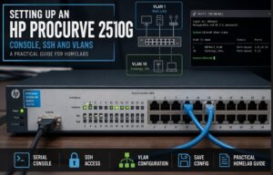

It provides managed Gigabit Ethernet, VLAN support, a proper command-line interface and remote management over SSH. For learning networking or building a more advanced home network, switches like this still have plenty of life left in them.
This guide covers the initial setup of an HP ProCurve 2510G using PuTTY, including connecting through the serial console, assigning a management IP address, enabling SSH and creating a simple isolated VLAN.
What You’ll Need
For the initial setup you’ll need:
- HP ProCurve 2510G switch
- serial console cable
- USB-to-RS232 adapter if your computer doesn’t have a serial port
- PuTTY on a Windows PC
- Ethernet cable
- access to your local network
Once the management IP has been configured, the serial connection is normally only needed for recovery or major configuration changes.
Connecting Through the Serial Console
The safest way to configure an unknown switch is through its physical console port.
Connect the console cable between the ProCurve and your computer.
If you’re using a USB-to-serial adapter, open Windows Device Manager and look under:
Ports (COM & LPT)
You should see something similar to:
USB Serial Port (COM3)
Make a note of the COM port number.
Open PuTTY and select:
Connection type: Serial
Serial line:      COM3
Speed:            9600
The remaining serial settings should be:
Data bits:    8
Stop bits:    1
Parity:       None
Flow control: None
Click Open and press Enter.
You should now see the ProCurve console.
Depending on the switch configuration, it may open directly into the menu interface or display a CLI prompt.
The ProCurve Menu Interface
One thing I like about these older HP switches is that you don’t immediately need to know the CLI to configure them.
The built-in text menu provides access to most of the basic settings.
The main menu normally contains options similar to:
1. Status and Counters
2. Switch Configuration
3. Console Analysis
4. Reboot Switch
5. Command Line (CLI)
For an initial setup, most of the work can be completed from Switch Configuration.
You can also enter:
menu
from the CLI to return to the menu system.
Configuring the Management IP
Before the switch can be managed over the network, it needs an IP address.
From the menu open:
Switch Configuration
    ↓
IP Configuration / Network Setup
Depending on the firmware version, the exact wording may vary slightly.
The management address normally belongs to VLAN 1 unless you’ve deliberately created a separate management VLAN.
For example:
IP Config:       Manual
IP Address:      192.168.68.2
Subnet Mask:     255.255.252.0
Default Gateway: 192.168.68.1
Use values appropriate for your own network.
Alternatively, the switch can use DHCP and you can create a DHCP reservation on your router.
For infrastructure such as managed switches, I generally prefer a predictable address so I always know where the management interface lives.
Configuring the IP from the CLI
The same configuration can be performed from the command line.
Select:
5. Command Line (CLI)
Then enter:
enable
configure terminal
vlan 1
ip address 192.168.68.2 255.255.252.0
exit
ip default-gateway 192.168.68.1
write memory
The prompts change as you move through the different configuration levels.
For example:
ProCurve>
ProCurve#
ProCurve(config)#
ProCurve(vlan-1)#
A useful rule of thumb is:
>           Normal command mode
#           Privileged mode
(config)#   Global configuration
(vlan-x)#   VLAN configuration
Enter:
enable
to move from:
ProCurve>
to:
ProCurve#
Then:
configure terminal
enters configuration mode.
Testing Network Access
Once the management address has been configured, connect one of the switch ports to your network.
From another computer, test the address:
ping 192.168.68.2
If the switch responds, network management is working.
At this point the serial cable is no longer required for normal administration.
Telnet Access
The 2510G can be managed using Telnet.
In PuTTY, select:
Connection type: Telnet
Host:            192.168.68.2
Port:            23
Telnet is useful for initial troubleshooting, particularly on older equipment, but I wouldn’t leave it as the primary management method.
Telnet sends commands and credentials across the network without encryption.
SSH is the better option.
Enabling SSH
Connect through the console or Telnet and enter privileged configuration mode:
enable
configure terminal
Generate an SSH host key:
crypto key generate ssh
Then enable SSH:
ip ssh
Save the configuration:
write memory
Once you’ve confirmed SSH works, Telnet can be disabled:
configure terminal
no telnet-server
write memory
I prefer doing this only after testing SSH from another computer. That way, if something is wrong with the SSH configuration, you haven’t accidentally removed your existing remote management method.
Connecting with SSH
Open PuTTY again and configure:
Host:            192.168.68.2
Port:            22
Connection type: SSH
Click Open.
The first time you connect, PuTTY will normally display a warning about the switch’s SSH host key.
Accept the key if you’re satisfied you’re connecting to the correct device.
You should then reach the ProCurve login or CLI prompt.
Configuring a Manager Password
An unmanaged password configuration isn’t something I’d leave in place.
On ProCurve switches, the Manager account provides privileged administrative access.
A password can be configured from the menu interface or CLI.
The exact commands available can vary depending on firmware, so it’s worth checking the installed software version before following configuration examples from newer Aruba switches.
You can check the switch version with:
show version
Once authentication is configured, use that account when connecting through SSH.
Naming the Switch
Giving infrastructure a meaningful hostname makes the CLI considerably easier to work with.
From configuration mode:
hostname OutworldCore
The command prompt will then change from something generic such as:
ProCurve#
to:
OutworldCore#
Save the change:
write memory
It’s a small thing, but once you have multiple switches and servers it makes identifying equipment much easier.
Understanding VLANs on the ProCurve
The next useful feature to configure is VLANs.
A VLAN creates a separate Layer 2 broadcast domain on the same physical switch.
For a home lab, this can be useful for separating things such as:
Main LAN
Servers
IoT
Guest devices
Test networks
Lab equipment
On HP ProCurve switches you’ll frequently see ports described as either tagged or untagged.
An untagged port is typically used for an ordinary end device.
For example:
PC
Printer
NAS
Raspberry Pi
The connected device doesn’t need to understand VLAN tagging.
A tagged port can carry multiple VLANs and is typically used between VLAN-aware devices such as:
Managed switch
Router
Firewall
Hypervisor
VLAN-aware access point
This is broadly equivalent to the access-port and trunk concepts used by other switch vendors, although the terminology differs.
Creating VLAN 10
For this example I’m creating:
VLAN ID:   10
VLAN Name: Synology_10x
The idea is to place two physical ports into their own Layer 2 network.
In my original setup these were:
Port 9  → Synology secondary LAN interface
Port 13 → Test client
Traffic between those ports remains within VLAN 10 unless another VLAN-aware device such as a router is deliberately configured to route between VLAN 10 and the rest of the network.
Creating VLAN 10 from the Menu
Open:
Switch Configuration
    ↓
VLAN Menu
    ↓
VLAN Names
Choose Edit and create:
VLAN ID:   10
VLAN Name: Synology_10x
Save the configuration.
Now open:
VLAN Port Assignment
Select VLAN 10.
Configure:
Port 9:  Untagged
Port 13: Untagged
Other ports can remain set to:
No
Those two ports now belong to VLAN 10 as untagged access ports.
Removing the Ports from VLAN 1
An untagged port should only belong to one untagged VLAN at a time.
Select:
VLAN 1
and remove ports 9 and 13 from the default VLAN.
The resulting arrangement should be:
VLAN 1
Ports 9,13: No

VLAN 10
Ports 9,13: Untagged
Save the changes.
Creating the VLAN from the CLI
The same configuration is much quicker once you’re comfortable with the CLI.
Enter configuration mode:
enable
configure terminal
Create VLAN 10:
vlan 10
name "Synology_10x"
Remove ports 9 and 13 from VLAN 1:
vlan 1
no untagged 9,13
Then assign them to VLAN 10:
vlan 10
untagged 9,13
exit
Finally:
write memory
Checking the VLAN Configuration
To inspect VLAN 10:
show vlans 10
You should see ports 9 and 13 associated with the VLAN.
You can also inspect the complete VLAN configuration:
show vlans
For more detail about the current switch configuration:
show running-config
These commands are extremely useful when troubleshooting because they show what the switch is actually running rather than what you think you’ve configured.
Testing the Isolated Network
In my example, LAN 2 on the Synology was configured on a separate network:
192.168.10.4
The Synology DHCP server could then provide addresses such as:
192.168.10.10
        ↓
192.168.10.50
With the Synology connected to port 9 and a test device connected to port 13, the DHCP process looks like this:
Test Device
    │
 Port 13
    │
 VLAN 10
    │
 Port 9
    │
 Synology LAN 2
    │
 DHCP Server
The DHCP broadcast remains inside VLAN 10 because VLAN 1 and VLAN 10 are separate Layer 2 broadcast domains.
The client should therefore receive an address from the Synology rather than from the DHCP server on the main LAN.
VLAN Isolation and Routing
It’s important to distinguish VLAN separation from complete security isolation.
A VLAN provides Layer 2 separation.
Devices in VLAN 10 cannot simply communicate directly with devices in VLAN 1 through the switch.
However, if a router, firewall or Layer 3 device is later configured to route traffic between those VLANs, communication can become possible.
The security boundary then depends on the firewall and routing rules configured on that device.
So rather than thinking of a VLAN as an absolute wall, I treat it as one part of the overall network design.
For this simple two-port test network, no inter-VLAN routing was configured, so the Synology and test client remained separated from the main LAN at Layer 2.
Saving the Configuration
One of the most important commands on these switches is:
write memory
Configuration changes are initially made to the running configuration.
Running:
write memory
stores them so they remain after a reboot.
You can also use:
show running-config
to inspect the active configuration before saving.
The menu interface normally saves changes when you select its Save option, but from the CLI I make a habit of explicitly running:
write memory
after completing a configuration change.
Useful ProCurve Commands
A few commands are worth remembering:
show version
Displays the switch model, firmware and system information.
show interfaces
Shows interface information.
show vlans
Displays configured VLANs.
show mac-address
Shows MAC addresses learned by the switch.
show running-config
Displays the active configuration.
show config
Displays the saved configuration.
menu
Returns to the text menu interface.
write memory
Saves the running configuration.
reload
Reboots the switch.
The Result
The HP ProCurve 2510G is old-school networking in the best possible way.
There’s no cloud account, mobile app or subscription. You connect a console cable, give the switch an IP address and configure exactly what you want it to do.
After the initial setup my switch had:
Serial console access
        ↓
Management IP
        ↓
SSH management
        ↓
Telnet disabled
        ↓
Named switch
        ↓
VLAN configuration
        ↓
Isolated test network
For a home lab, it’s also a useful way of learning how managed networking actually works.
Concepts such as tagged and untagged ports, VLAN membership, management interfaces, SSH access and Layer 2 isolation are exactly the same concepts used in much larger networks.
The hardware may be getting on a bit, but as a managed Gigabit lab switch the ProCurve 2510G can still be surprisingly useful.
:::